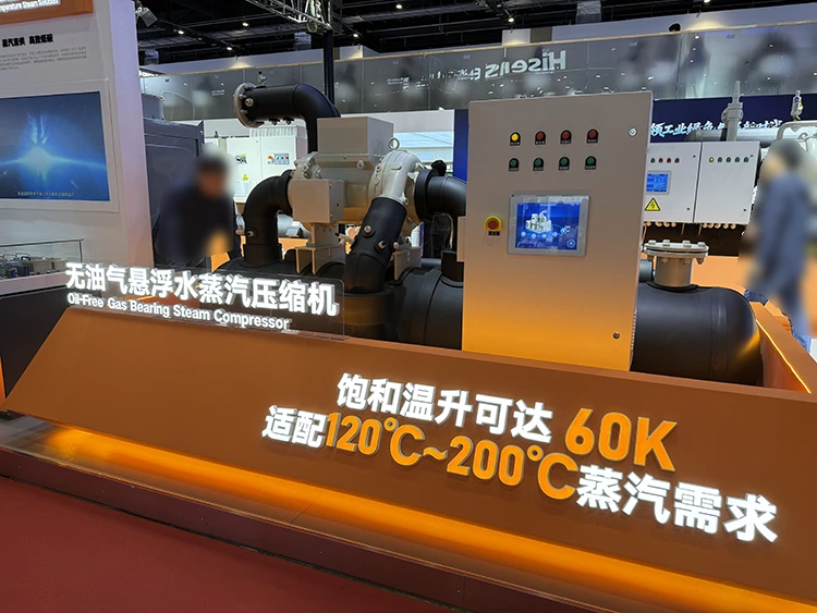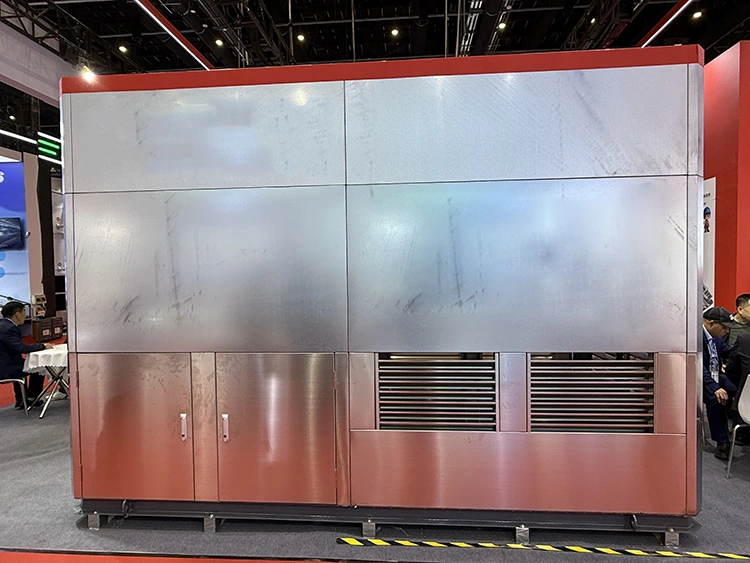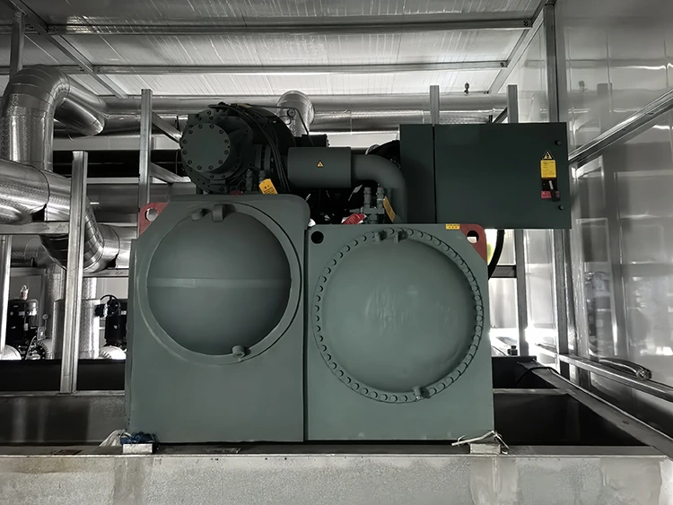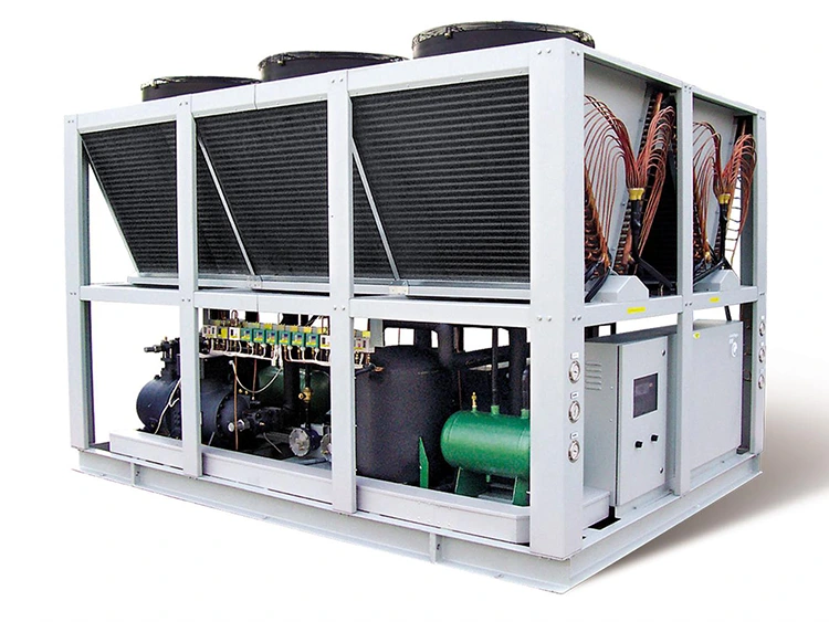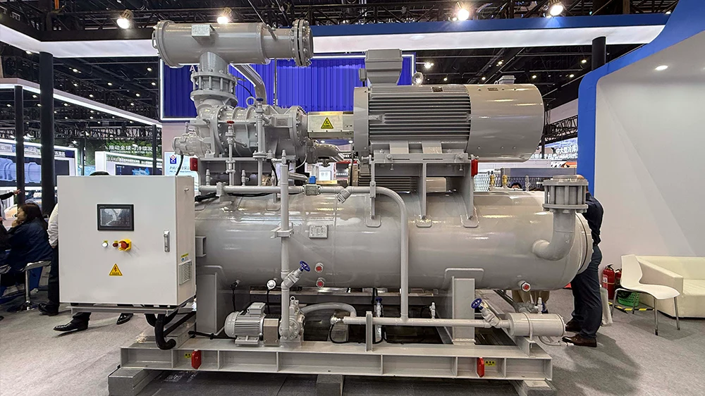
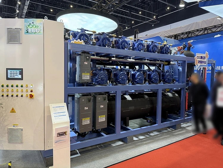
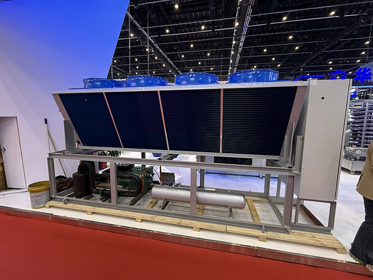
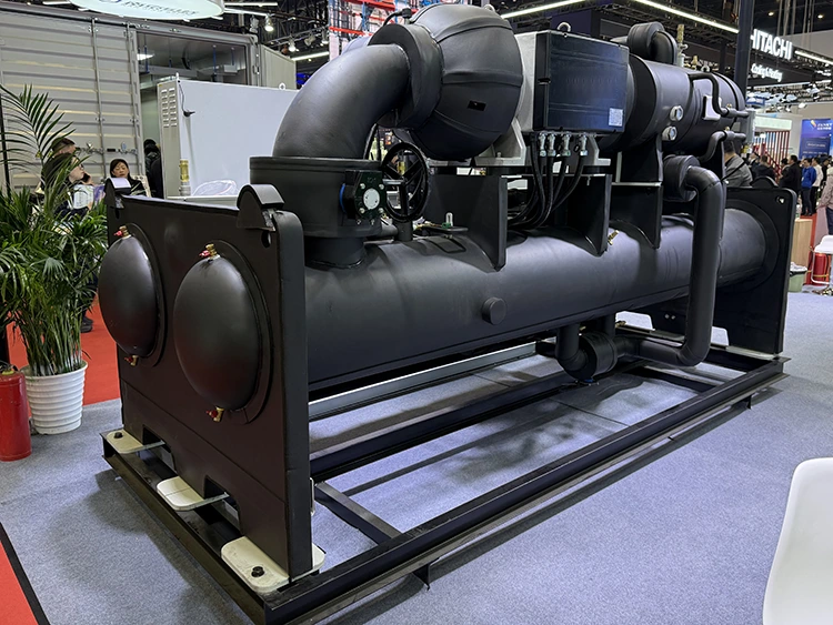
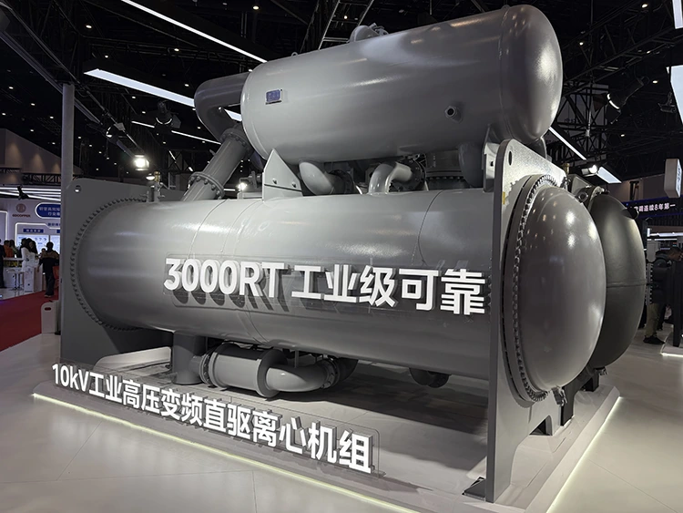
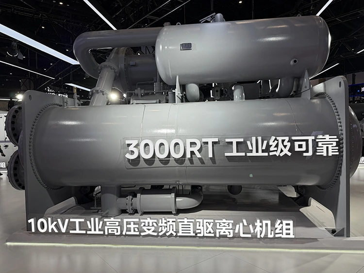
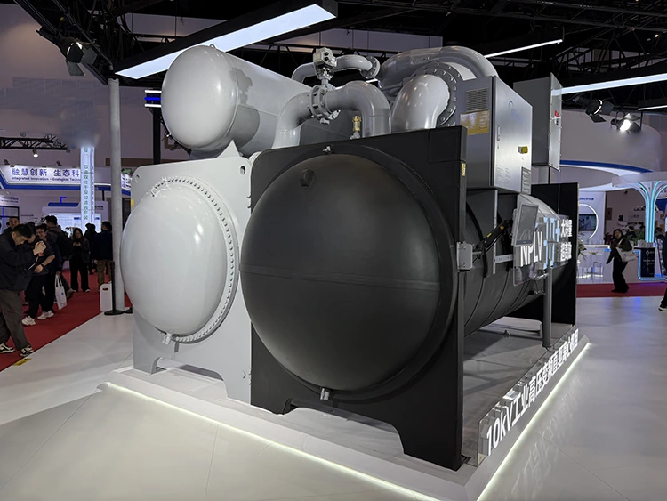
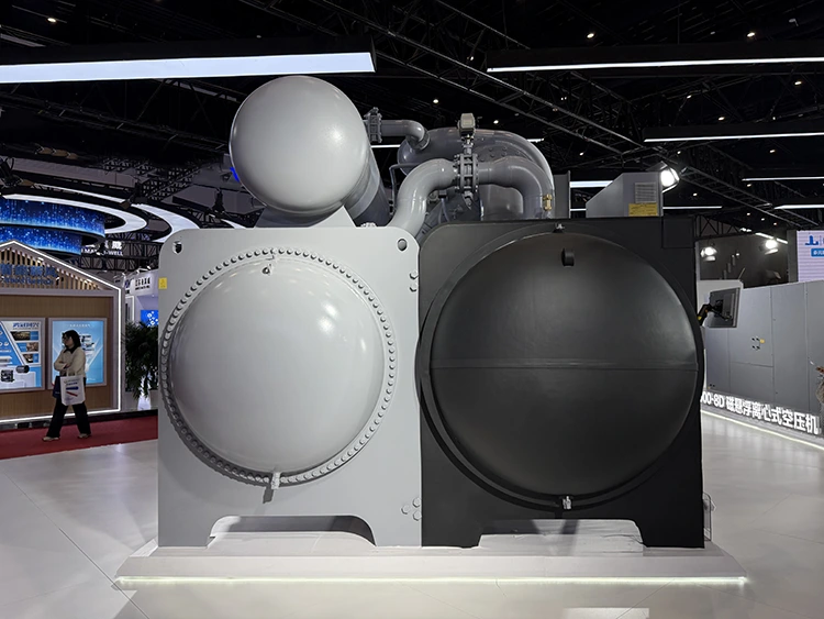
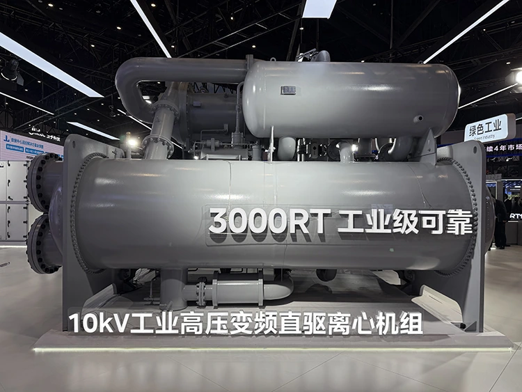
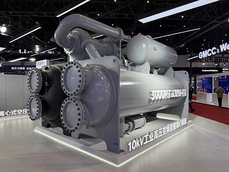
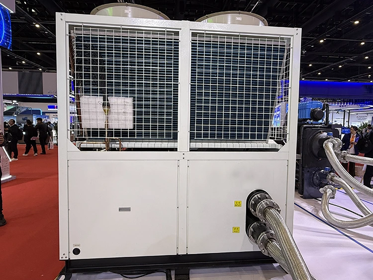
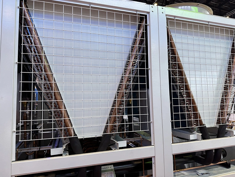
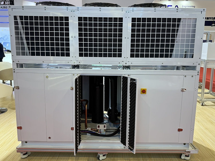
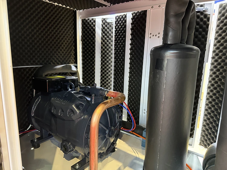
Magnetic Levitation Centrifugal Chiller Unit
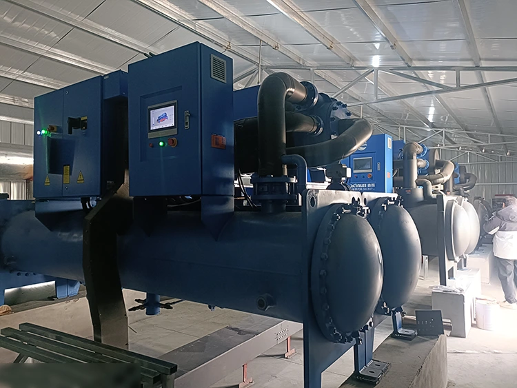
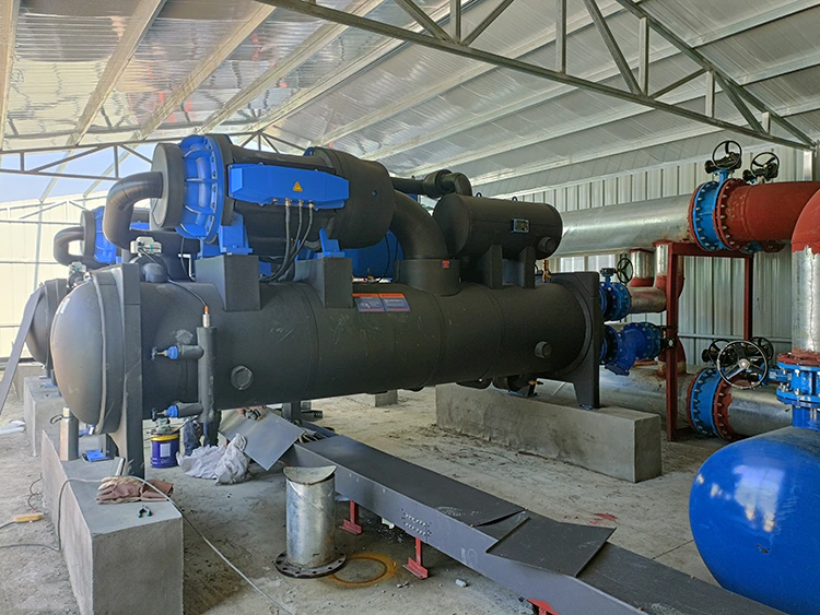
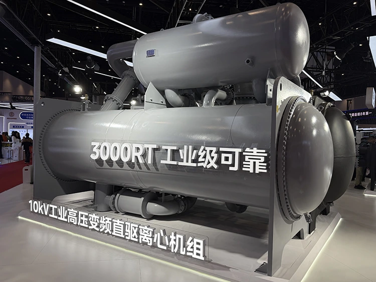
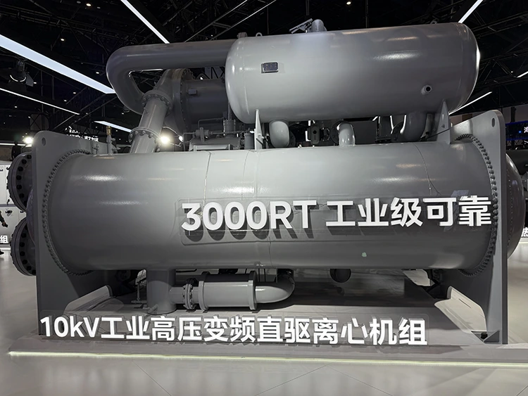
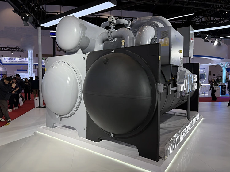
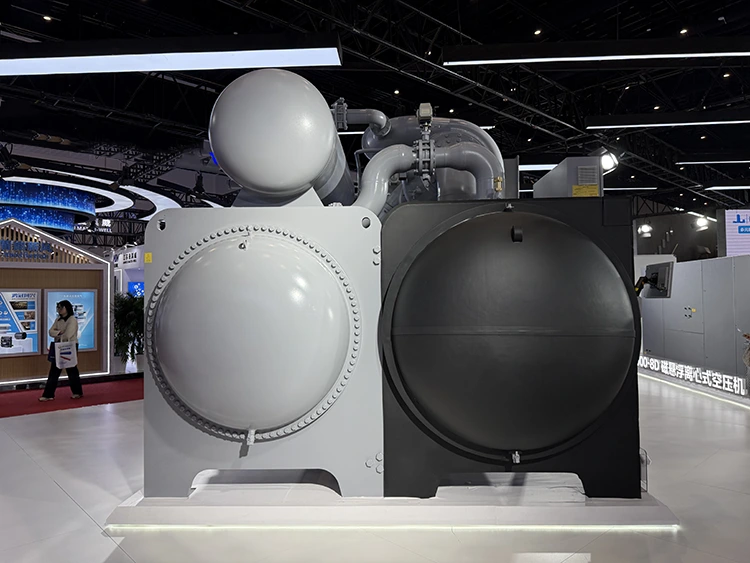
Magnetic Levitation Centrifugal Chiller Unit is a complete refrigeration system built around a magnetic bearing centrifugal compressor, combined with an evaporator, condenser, expansion device, and intelligent control system. The unit is designed for medium and large commercial buildings, data centers, industrial plants, cold chain logistics centers, and pharmaceutical manufacturing facilities where reliable chilled water supply is required for HVAC and process cooling applications.
Within Lynxcool’s refrigeration solution portfolio, the Magnetic Levitation Centrifugal Chiller Unit is not supplied as a standalone standard product. Instead, it serves as a core cooling source module within an integrated refrigeration system. Based on project cooling load requirements, annual load variations, cooling water conditions, and terminal equipment configuration, Lynxcool provides complete system engineering, including chiller selection, piping design, hydraulic calculation, and control strategy development.
The final value delivered to customers comes from both the technical performance of the chiller itself and Lynxcool’s experience in refrigeration system engineering and project implementation.
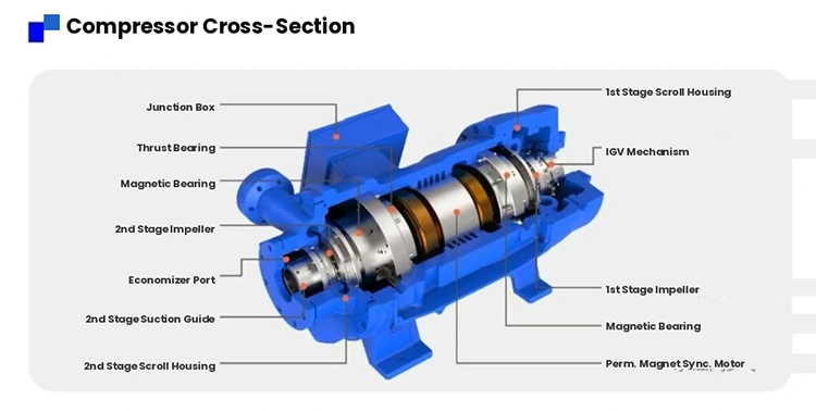
Compressor Structure: Magnetic Bearing and Permanent Magnet Synchronous Motor
The compressor is the core component of the centrifugal chiller. The magnetic levitation centrifugal compressor uses an active magnetic bearing system, which suspends the rotor at the center position through electromagnetic force during operation. Since there is no physical contact between the rotor and stator, mechanical friction between rotating components is eliminated.
The magnetic bearing system uses displacement sensors to monitor rotor position in real time. The controller adjusts the current flowing through electromagnetic coils according to sensor feedback, maintaining the rotor within the designed levitation clearance during operation.
The compressor is driven by a permanent magnet synchronous motor (PMSM). Permanent magnets are embedded inside the rotor, and the rotating magnetic field generated by the energized stator directly drives the rotor. The motor and impeller are connected through a direct coaxial structure, eliminating traditional speed-increasing gears and couplings.
By simplifying the transmission structure, the number of mechanical moving parts is reduced, while mechanical losses, vibration, and operating noise caused by gear transmission are avoided.
The impeller adopts a three-dimensional flow design. Through computational fluid dynamics (CFD) optimization, the blade profile and flow channel geometry are designed to improve gas compression efficiency during high-speed rotation.
Refrigeration Cycle and Heat Exchange System
The unit adopts a vapor compression refrigeration cycle, in which the refrigerant completes four processes within a closed system: compression, condensation, expansion, and evaporation.
The evaporator adopts a flooded type or falling film heat exchanger design. Chilled water flows inside the tubes, while refrigerant circulates on the shell side. The liquid refrigerant absorbs heat from the chilled water in the evaporator shell side and evaporates into vapor, reducing the chilled water temperature to the preset value.
High-efficiency heat transfer tubes are installed inside the evaporator. The outer surface of the tubes is specially treated to increase heat transfer area and improve boiling heat transfer performance.
The compressor draws low-temperature and low-pressure refrigerant vapor generated in the evaporator. After being compressed by the high-speed rotating impeller, the refrigerant becomes high-temperature and high-pressure gas and enters the condenser.
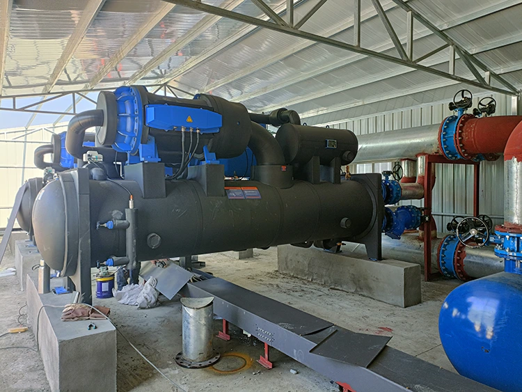
The condenser generally adopts a water-cooled shell-and-tube structure. Cooling water flows inside the tubes, while refrigerant condenses on the shell side and releases heat, changing from high-pressure gas into high-pressure liquid.
The condenser heat transfer tubes are also designed with high-efficiency threaded tubes or enhanced surface tubes to improve heat exchange performance and reduce water-side pressure drop.
The high-pressure liquid refrigerant passes through the expansion device, such as an electronic expansion valve or fixed orifice, where pressure and temperature are reduced before entering the evaporator. This completes the refrigeration cycle.
Key Technical Specifications
|
Parameter |
Specification |
|
Series |
SMP |
|
Unit Type |
Magnetic Levitation Variable Frequency Centrifugal Chiller |
|
Compressor |
Swedish SRM Magnetic Levitation VFD Centrifugal |
|
Refrigerant |
R134a |
|
Bearing Technology |
Active Magnetic Levitation (Oil-Free) |
|
Motor Type |
Permanent Magnet Variable Frequency |
|
Evaporator Type |
High-Efficiency Flooded Shell-and-Tube |
|
Condenser Type |
Shell-and-Tube (Water-Cooled) |
|
Capacity Modulation |
Stepless — Variable Speed (VFD) + Built-in IGV |
|
Lubrication System |
None Required (Completely Oil-Free) |
|
Starting Current |
Low (VFD Soft Start) |
|
Heat Transfer Tubes |
High-Efficiency Enhanced Tubes |
|
System Valves |
Premium First-Tier International Brands |
|
Power Failure Protection |
Dedicated Bearing Backup Power Supply |
|
Primary Applications |
Office Buildings, Hospitals, Electronics Factories, Data Centers |
Oil-Free Operation and Heat Transfer Efficiency
Traditional screw or centrifugal compressors rely on lubricating oil to reduce friction between bearings and rotating components. During operation, a certain amount of oil may enter the refrigeration circuit with the refrigerant and circulate through the evaporator and condenser.
At the low-temperature side of the evaporator, lubricating oil viscosity increases and may accumulate on the surface of heat transfer tubes, creating additional thermal resistance. This reduces evaporating efficiency and gradually affects the heat transfer performance of the chiller.
To maintain operating efficiency, conventional systems usually require regular maintenance of oil separators, oil return systems, and heat exchanger tube cleaning.
The magnetic levitation compressor operates without lubricating oil. Since no oil enters the refrigeration circuit, the heat transfer surfaces of the evaporator and condenser remain clean during the service life of the equipment.
As a result, the heat transfer performance does not gradually decrease due to oil contamination. Under normal operating conditions, the cooling capacity and energy efficiency ratio can remain close to the factory-rated values after several years of operation.
Variable Frequency Drive and Capacity Control
The chiller uses variable frequency drive technology to adjust compressor speed according to actual cooling demand.
The controller continuously compares the chilled water outlet temperature with the preset value and adjusts the compressor motor speed to match the current load requirement. Under partial load conditions, the motor operates below the rated speed, reducing impeller speed and compressor capacity. The power consumption decreases significantly as the rotational speed is reduced.
The inverter integrates PID control algorithms and load prediction functions. By analyzing the rate of chilled water temperature change, the control system dynamically adjusts compressor speed to prevent frequent start-stop operation and large temperature fluctuations.
Once the chilled water temperature reaches the set point, the unit can continue operating at a lower speed level, maintaining stable outlet water temperature while reducing energy consumption.
Comparison: SMP Series vs Conventional Centrifugal Chillers
|
Performance Parameter |
Conventional Centrifugal Chiller |
SMP Magnetic Levitation Centrifugal Chiller Unit |
|
Bearing Type |
Oil-Lubricated Contact Bearings |
Active Magnetic Levitation |
|
Lubrication Oil System |
Required (Complex) |
Not Required (Eliminated) |
|
Mechanical Friction |
Present |
Zero |
|
Heat Exchanger Oil Fouling |
Progressive Performance Degradation |
None — Sustained Peak Efficiency |
|
Vibration Level |
Moderate |
Very Low |
|
Noise Level |
Moderate |
Very Low |
|
Vibration Isolation Required |
Yes |
Not Required |
|
Acoustic Plant Room Required |
Often Required |
Not Required |
|
Starting Current |
High (Grid Disturbance) |
Low (VFD Soft Start) |
|
Part-Load Efficiency |
Degrades with Load Reduction |
Maintained at High Level |
|
Maintenance Complexity |
Oil System Management Required |
Minimal — No Oil System |
|
Service Life |
Dependent on Bearing Wear |
Extended — No Wear Mechanism |
Evaporator and Condenser Selection
The heat transfer area of the evaporator and condenser directly affects the cooling capacity and energy efficiency of the chiller. During project design, Lynxcool selects and configures heat exchangers according to the customer’s chilled water inlet and outlet temperatures, cooling water conditions, water quality requirements, and fouling factors.
For applications requiring higher inlet water temperatures or lower chilled water outlet temperatures, the evaporator can be designed with a larger heat transfer area to maintain an appropriate temperature difference between the refrigerant evaporation temperature and chilled water outlet temperature, typically within 4–6℃.
For projects located in areas with high water hardness, the condenser tube wall thickness and internal water velocity can be optimized to reduce scale formation and minimize corrosion risks.
Cleaning ports are reserved on both ends of the condenser water box, allowing convenient mechanical cleaning or chemical cleaning during future maintenance.
Electronic Expansion Valve and Refrigerant Flow Control
The unit uses an electronic expansion valve instead of traditional thermal expansion valves or fixed orifice devices. Driven by a stepper motor, the valve needle position can be precisely adjusted to control refrigerant flow.
The control system regulates the opening degree of the electronic expansion valve according to real-time operating parameters, including evaporator outlet refrigerant superheat, compressor suction pressure, and discharge temperature.
By continuously adjusting refrigerant flow, the system ensures that the refrigerant supply matches the current cooling load and allows the evaporator heat transfer area to be fully utilized.
The electronic expansion valve provides fast response speed and a wide adjustment range. During startup, it gradually increases refrigerant flow to reduce the risk of liquid refrigerant entering the compressor.
Under partial load operation, the valve maintains an appropriate opening position to ensure stable evaporation conditions and efficient heat transfer performance.
Intelligent Control System
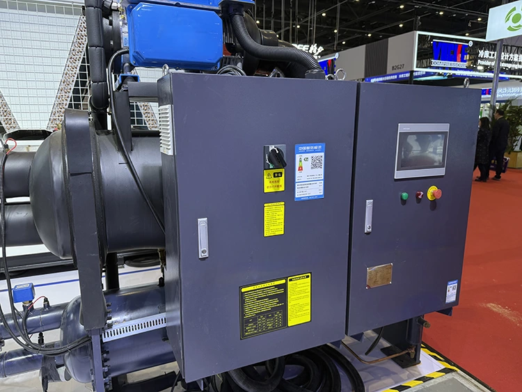
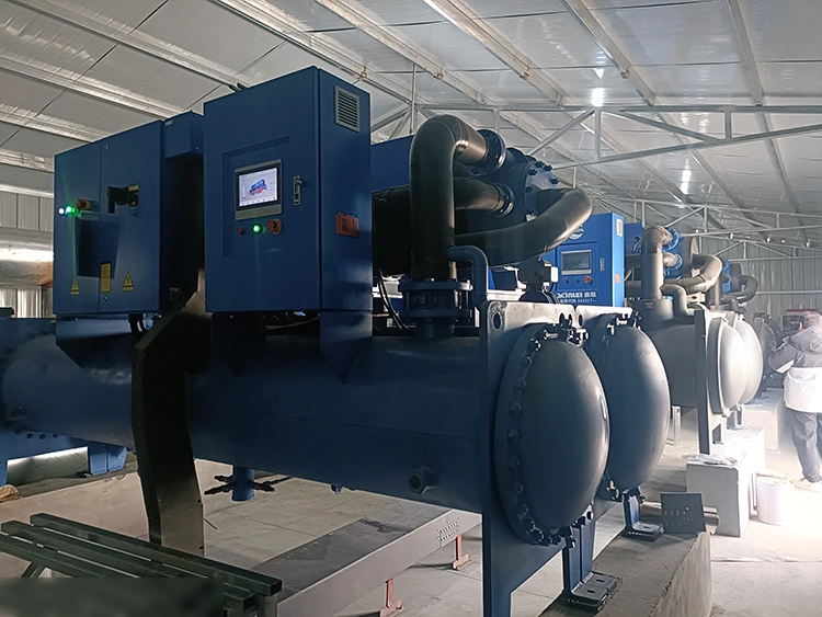
The chiller control system is developed based on an industrial-grade PLC platform and equipped with a touchscreen human-machine interface (HMI).
The control logic includes compressor start and stop control, speed regulation, expansion valve adjustment, chilled water pump interlock, freeze protection, high and low pressure protection, discharge temperature protection, overload protection, phase loss protection, and water flow switch monitoring.
Operating parameters are displayed and recorded in real time through the control interface, including:
Chilled water inlet and outlet temperature
Cooling water inlet and outlet temperature
Evaporation pressure
Condensing pressure
Discharge temperature
Motor current
Bearing clearance
Bearing temperature
Vibration value
Compressor speed
Operating hours
The control system supports standard communication protocols, including Modbus RTU and optional Modbus TCP/IP. It can exchange data with building automation systems (BAS) or factory energy management systems (EMS).
Remote monitoring can be achieved through wired networks or 4G wireless modules. Operation personnel can remotely check equipment status, receive fault alarms, and adjust operating parameters without being physically present at the equipment site.
Cooling Water System Adaptability and Operating Range
The magnetic levitation centrifugal chiller has a wide operating range for cooling water inlet temperature conditions. When the cooling water temperature is relatively low, such as during winter or transitional seasons, the unit can operate under lower condensing pressure, resulting in reduced compressor power consumption.
The condenser pressure control function ensures stable operation when the cooling water temperature is lower than the design condition. The control system prevents unstable operation caused by refrigerant migration or excessively low compression ratio.
The maximum allowable cooling water inlet temperature is generally 35–38℃, depending on the compressor model and refrigerant type.
The chilled water outlet temperature setting range is typically 5–20℃. For standard air-conditioning applications, the typical chilled water condition is 7℃ outlet water and 12℃ return water. For industrial process cooling, the outlet temperature can be adjusted according to process requirements, commonly within the range of 5–10℃.
Surge Control and Operating Stability
Centrifugal compressors may experience surge conditions under low-load operation or high condensing pressure. Surge occurs when airflow reverses at the impeller outlet, causing pressure fluctuations and unstable compressor operation. In severe cases, continuous surge operation may damage the impeller.
The magnetic levitation centrifugal compressor uses active control technology to prevent surge. The controller continuously monitors operating parameters, including motor current, compressor speed, suction pressure, and discharge pressure.
When the operating point approaches the surge boundary, the control system automatically adjusts compressor speed or inlet guide vane position (if equipped) to move the operating condition back into a stable range.
Under abnormal conditions, such as excessive cooling water temperature or sudden reduction in chilled water flow, the controller prioritizes protective unloading and alarm functions to prevent the compressor from entering the surge area.
Model Selection and Performance Rating
The standard selection condition for the chiller is based on:
Chilled water inlet/outlet temperature: 12℃ / 7℃
Cooling water inlet/outlet temperature: 30℃ / 35℃
Ambient temperature: 35℃
Under these conditions, the cooling capacity range of the unit typically covers 300 kW to 2000 kW.
The integrated part-load value (IPLV) can reach 8.0–9.5 depending on the selected model and operating conditions.
Actual cooling capacity and energy efficiency vary according to site conditions. During the selection process, Lynxcool evaluates project information including:
Annual average wet-bulb temperature at the installation location
Cooling tower design parameters
Annual chilled water load distribution
Operating schedule and load characteristics
These parameters are used to determine the most suitable chiller configuration for each project.
Installation Conditions and Machine Room Requirements
Compared with traditional screw chillers, magnetic levitation centrifugal chillers have lower requirements for installation foundations.
Due to the non-contact magnetic bearing structure, vibration transmission during operation is extremely low. Both dynamic and static loads are reduced, making the unit suitable for projects with strict vibration control requirements.
The compact structure allows the unit to occupy less installation space. Under the same cooling capacity, the footprint can be reduced by approximately 30%–40% compared with conventional screw chiller systems.
The recommended machine room clear height is generally 3.5–4.5 meters. Sufficient maintenance clearance should be reserved around the unit, and adequate space should be provided at both ends of the evaporator and condenser for heat exchanger tube removal and servicing.
Cooling water and chilled water connections use standard flange connections. Before shipment, the unit is partially charged with refrigerant and filled with protective inert gas. After installation, the remaining refrigerant is added, followed by system commissioning.
Maintenance Schedule and Inspection Requirements
Routine maintenance of Magnetic Levitation Centrifugal Chiller Units mainly includes:
Weekly inspection:
Check chilled water and cooling water inlet/outlet temperatures
Check temperature difference between inlet and outlet water
Monthly inspection:
Check electrical terminal tightness
Review touchscreen operation records and alarm history
Quarterly inspection:
Check pressure drop across evaporator and condenser water sides
Clean heat exchangers if pressure drop exceeds 15% of the initial value
Semi-annual inspection:
Calibrate temperature and pressure sensor accuracy
Clean chilled water filters
Annual inspection:
Replace chilled water and cooling water if required
Perform water quality testing
Check aging condition of electrical components
The magnetic bearing system does not require regular oil replacement or lubrication. Bearing position and operating status are continuously monitored by the controller. If abnormal conditions occur, the system generates an alarm, and professional technicians can perform diagnosis using dedicated service tools.
Typical Application Scenarios
Data Center Cooling
Data centers operate continuously throughout the year and require stable cooling performance with strict energy efficiency requirements.
The magnetic levitation centrifugal chiller is suitable for data center cooling systems due to its high efficiency under partial load conditions. Its operating characteristics match the variable load patterns of IT equipment, helping reduce annual cooling energy consumption and improve overall data center energy performance.
Pharmaceutical and Biotech Manufacturing
Pharmaceutical production areas require precise chilled water temperature control and reliable continuous operation.
The Magnetic Levitation Centrifugal Chiller Unit can maintain chilled water outlet temperature control accuracy within ±0.5℃. The control system supports multiple unit configurations, including standby operation and coordinated control logic, to improve system reliability for critical production environments.
Food Processing and Cold Chain Logistics
Food processing facilities and cold storage warehouses often require refrigeration systems operating across multiple temperature ranges.
Combined with Lynxcool’s refrigeration system design capability, including evaporator, condenser, and air cooler selection, the Magnetic Levitation Centrifugal Chiller Unit can be integrated into multi-temperature cooling systems.
For large cold chain logistics centers, the low operating noise of the unit helps reduce the impact on warehouse personnel and daily operations.
Plastic and Rubber Processing
Injection molding machines and extrusion equipment require stable chilled water supply for mold cooling and process temperature control.
During long-term continuous operation, the magnetic levitation chiller maintains consistent heat transfer performance without oil contamination inside the refrigeration circuit, helping ensure stable mold temperature control and product dimensional accuracy.
Large Commercial Buildings and District Cooling Systems
Shopping malls, office buildings, hospitals, airports, and other large public facilities typically experience significant cooling load variations throughout the day.
The magnetic levitation centrifugal chiller can adjust capacity smoothly under different load conditions, providing efficient operation during both daytime high-load periods and nighttime low-load periods.
Lynxcool Project Delivery Process
In actual project implementation, Lynxcool provides the Magnetic Levitation Centrifugal Chiller Unit as part of a complete cooling system solution rather than only supplying the equipment.
After receiving the customer's basic project information, including building type, HVAC or process cooling requirements, estimated cooling load, and local climate conditions, Lynxcool's engineering team performs system load calculation and equipment selection.
After the chiller model is confirmed, the engineering team completes the design of the chilled water system, cooling water system, pump selection, expansion tank selection, and pipeline insulation方案, and provides complete construction drawings.
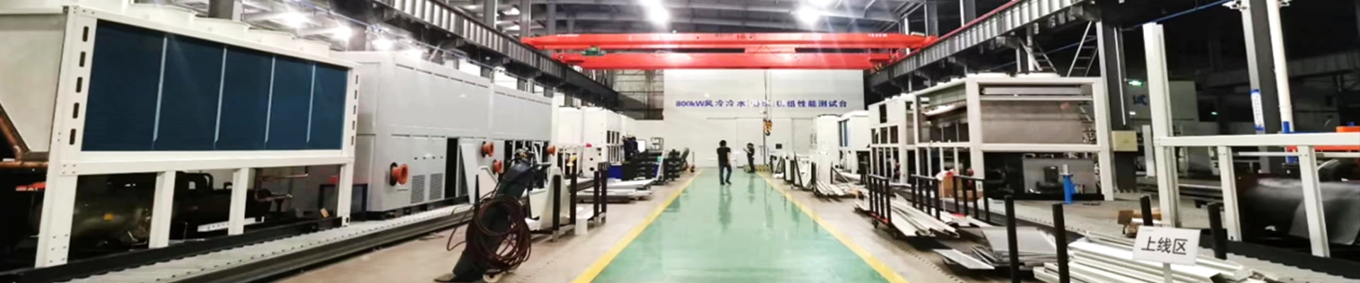
During the manufacturing stage, Lynxcool coordinates equipment production and material preparation according to the approved technical specifications. Installation is carried out by qualified engineering teams with pressure pipeline installation and mechanical-electrical installation capabilities.
The on-site installation process includes:
- Refrigeration and water piping connection
- Electrical wiring
- System flushing
- Hydraulic pressure testing
- Vacuum testing
During commissioning, technicians complete refrigerant charging, parameter setting, control logic verification, and load testing.
After all operating indicators meet the design requirements, the system is handed over to the customer together with operation training and maintenance guidance.
Through complete engineering support from equipment selection to commissioning, Lynxcool helps customers build stable and efficient chilled water systems for commercial, industrial, and process cooling applications.
Hot Tags: Magnetic Levitation Centrifugal Chiller Unit supplier, refrigeration unit factory, energy saving chiller
Send Inquiry
Contact Info
-
Address
No. 1 Zhengzhou Road, Shibei District, Qingdao City, Shandong Province, China
-
Tel
-
E-mail
Welcome to send your detailed demands for Refrigeration Compressor Unit, Screw Compressor Unit, Evaporator. Our professional sales team from this China refrigeration manufacturer will reply quickly, provide custom plans and one-stop purchasing service.